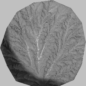
cropped reduced digital photograph, run 4
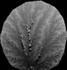
gridded elevation, 4 mm spacing (white = highs, black = lows)
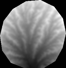
filtered and smoothed elevation
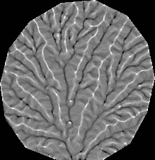
local relative height (5x5 moving window)
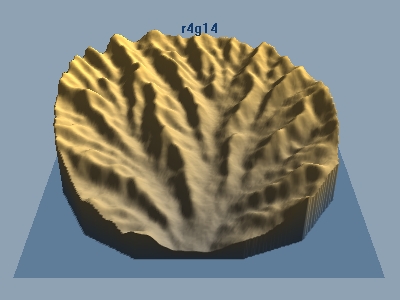
oblique 3-d view
In order to address issues related to landscape form, we used stereo digital
photographs to develop gridded elevation models of the landform. The process
involves several steps. First, the photographs are rotated 90 degrees into rough
parallelism with the basin reference frame, and converted to gray scale (pixel
values 0-255). Photographic coordinates of measured benchmarks on the basin
walls were collected for each photograph. The stereo pairs were then cropped,
and automatically correlated at an arbitrary grid spacing, usually every 4-8
pixels. To perform the correlation, a two dimensional projective transformation
was calculated for reference points appearing in both photographs:
x2 = (a1,1 * x1 + a1,2 * y1 + c1) / ( a3,1 * x1 + a3,2 * y1 + 1)
y2 = (a2,1 * x1 + a2,2 * y1 + c2) / ( a3,1 * x1 + a3,2 * y1 + 1),
where ai,j are elements in a scaling matrix, c1 and c2 are translation constants.
Given at least 4 correlated points in each photograph, the 8 transformation
parameters can be computed. We used from 4 to 14 correlated points and a least
squares inversion algorithm to determine the transformation parameters. As a
side note, a two dimensional conformal transformation was tried initially, but
this transform only works for photographic planes that are parallel to each
other, and does not account well for arbitrarily oriented photographs. Additionally,
the elevation field calculated (via collinearity) from a plane and a projective
transform of that plane results in another plane. The elevation field calculated
from a plane and a conformal transform of that plane is a curved surface. The
residual difference between measured correlated coordinates and transformed
coordinates is substantially smaller for a projective transform (~1-5 pixels)
as opposed to a conformal transform (~5-10 pixels). This fact allows for smaller
search regions in the target photograph during correlation, and corresponding
reductions in computing time.
The correlation proceeds by stepping across one of the photographs, transforming
the photographic coordinates into the second photograph, and searching the second
photograph for the smallest square root sum of squared differences between pixel
color values within a moving search box around the targeted transformed point.
During initial tests, it was discovered that an improved correlation could be
obtained by searching in the photographic offset direction (i.e., the flight
line direction), instead of searching in all directions around the target pixel.
The flight line direction can be calculated using a projective transform from
the ground reference frame to the target photograph, projecting camera ground
x and y coordinates onto the photograph, and calculating the direction between
camera coordinates in the photographic reference frame. This method of correlation
works moderately well, but is not bullet proof. Correlations also depend on
search window dimensions. Trial and error suggests that a window of 16 x 16
pixels and search distances ~10 pixels generate reasonable correlations in most
cases.
After correlation, camera orientations are calculated using the well-known collinearity
equations:
xp = foc * (A11 * delx + A12 * dely + A13 * delz
) / (A31 *delx + A32 * dely + A33 *delz )
yp = foc * (A21 * delx + A22 * dely + A23 * delz
) / (A31 *delx + A32 * dely + A33 *delz ),
delx = (xg - xci)
dely = (yg - yci)
delz = (zg - zci),
where p refers to photographic coordinates, g refers to ground
reference frame coordinates, ci refers to camera location coordinates
in the ground reference frame, foc is effective camera focal length in dimensions
of ground reference frame, and Aij is the rotation matrix,
A(1, 1) = Cos(phi) * Cos(kappa)
A(1, 2) = Cos(omega) * Sin(kappa) + Sin(omega) * Sin(phi) * Cos(kappa)
A(1, 3) = Sin(omega) * Sin(kappa) - Cos(omega) * Sin(phi) * Cos(kappa)
A(2, 1) = -Cos(phi) * Sin(kappa)
A(2, 2) = -Sin(omega) * Sin(phi) * Sin(kappa) + Cos(omega) * Cos(kappa)
A(2, 3) = Cos(omega) * Sin(phi) * Sin(kappa) + Sin(omega) * Cos(kappa)
A(3, 1) = Sin(phi)
A(3, 2) = -Sin(omega) * Cos(phi)
A(3, 3) = Cos(omega) * Cos(phi),
where omega is rotation around the x axis, phi is rotation around the y axis,
and kappa is rotation around the z axis. Angles are in radians. Positive rotations
indicate counterclockwise rotation when looking down the axis toward the origin.
The rotation matrix accounts for the rotations to go from the photographic to
the ground reference frame. A set of collinearity equations can be written for
any point appearing in a photograph. The collinearity equations contain 11 variables.
We treated measured ground control and photographic points and camera locations
as known variables, leaving 4 unknowns, the three rotations and effective camera
focal length. These can be determined if at least 2 ground control points are
known (i.e., 2 points yield 4 equations in 4 unknowns). Since the collinearity
equations are nonlinear, we employed a numerical scheme that linearized the
collinearity equations, and iterated until changes in the unknowns were negligible.
Once the camera parameters have been determined, ground coordinates of correlated
points can be calculated, again with collinearity equations. These ground coordinates
are then read into an arbitrarily spaced grid, filtered for extreme or missing
values, and smoothed. We report statistics on grids with 7 mm horizontal spacing.
The precision of photogrammetric solutions using a 1280 x 960 pixel resolution
camera is not all that impressive. Elevation ranges calculated for single pixel
shifts are in the range from 7 to 20 mm, depending on the distance between the
ground surface and camera and the field of view. The elevation models should
be viewed as approximations to the ground surface. Nonetheless, a fair amount
of detail can be discriminated from the elevation fields derived from this method.
page last modified June 11, 2001 by Les Hasbargen